
Views: 164 Author: Site Editor Publish Time: 2026-08-10 Origin: Site


Selecting the right friction material is a high-stakes engineering decision. Choosing a product based solely on a "high friction" marketing claim often ends badly. You risk accelerated equipment wear, sudden safety failures, and highly disruptive unplanned downtime. Heavy-duty industrial machinery, including overhead cranes, stamping presses, and massive winches, faces brutal operating conditions. These systems endure extreme load weights and punishing heat cycles daily. Standard automotive friction ratings simply cannot handle this intense mechanical stress.
Procurement and engineering teams need an evidence-based evaluation framework to make informed decisions. This guide breaks down how to properly evaluate friction metrics and their limitations. You will discover the delicate balance between stopping power and material longevity. By understanding these technical trade-offs, we can help you shortlist the perfect material formulation for your specific heavy-duty application.
A single friction coefficient number is insufficient; buyers must evaluate the friction curve across the equipment’s actual operating temperature range.
Higher friction often compromises wear resistance; optimizing for Total Cost of Ownership (TCO) requires balancing stopping power with drum/rotor longevity.
Static friction (holding power) and dynamic friction (stopping/slipping power) dictate whether a material is suited for a holding brake versus an industrial clutch.
Reliable suppliers provide verifiable lab test data (e.g., fade and recovery charts) rather than just generic industry edge codes.
Engineers often rely heavily on numerical ratings when specifying machine components. However, friction is not a static property. It is a dynamic system response. We must look closely at how static and dynamic friction values interact during operation. Static friction represents the holding power required to keep a stationary load from moving. Dynamic friction defines the stopping or slipping power while parts move against each other. Both metrics are absolutely critical for industrial machinery. An overhead crane requires immense static friction to hold a suspended load safely. Conversely, a high-speed stamping press relies on dynamic friction to decelerate heavy mechanisms smoothly.
Automotive suppliers often use standard DOT edge codes like EE, FF, or GG. These two-letter codes provide a helpful baseline for passenger vehicles and commercial fleets. They indicate a broad general friction range measured at low and high temperatures. However, industrial buyers need far more precise data. Broad alphabetical ranges obscure critical performance gaps. You need specific numerical data points mapped across varying speeds and pressures. A reliable friction coefficient for industrial applications typically ranges from 0.15 to 0.60 µ depending on the specific mechanical requirements.
Many procurement teams fall for the myth of "higher is better." They mistakenly assume maximum friction guarantees maximum safety. This assumption creates dangerous operational risks. An excessively high friction rating often causes aggressive, abrupt engagement. Operators experience this as intense grabbing or violent chattering. Such shock loading damages expensive drive components quickly. It tears apart gearboxes, snaps drive shafts, and puts plant workers at serious risk. The goal is never the highest possible number. The actual goal is a stable, predictable coefficient matching your specific operational requirements.
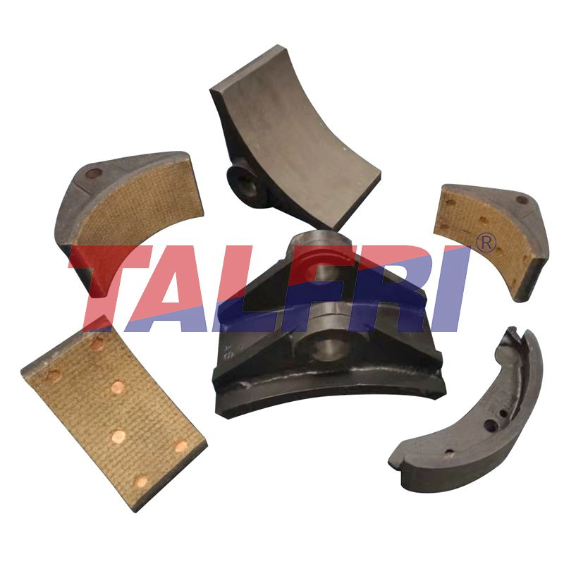
Braking systems convert kinetic energy directly into thermal energy. This heat generation is completely unavoidable. As heavy machinery operates, internal surface temperatures spike rapidly. This intense heat attacks the chemical binder holding the friction material together. When organic resins overheat, they begin to vaporize. This rapid off-gassing creates a microscopic layer of gas between the brake pads and the rotor. The result is brake fade, which manifests as a sudden and dangerous drop in stopping power.
To combat fade, buyers must evaluate temperature resistance rigorously. Never accept a single peak friction number from a material supplier. Instead, always request detailed "fade and recovery" charts. These heat curves reveal exactly how a material performs over continuous, punishing heat cycles. The crucial metric here is thermal stability. You want a friction curve remaining relatively flat as temperatures climb. A material boasting a high initial bite but plummeting performance at 400°F is useless for heavy-duty repetitive applications.
Different compounds exhibit wildly different thermal behaviors. Understanding these material limitations helps narrow down your sourcing options significantly.
Material Compound | Thermal Tolerance | Performance Characteristics |
|---|---|---|
Woven Organics | Low to Moderate | Excellent low-temperature stability and quiet operation. Prone to fade under continuous heavy heat cycles. |
Molded Semi-Metallics | Moderate to High | Contains metal fibers transferring heat away from the friction surface. Resists fade better than standard organics. |
Sintered Metals | Extreme | Thrives in high-heat environments. Requires high operating temperatures to achieve optimal friction bite. |
You must match the compound directly to your machine's heat generation profile. Over-specifying a sintered metal for a low-heat, intermittent application leads to extremely poor cold-stopping performance. Under-specifying a basic organic compound for a high-heat tensioning application guarantees rapid failure and safety hazards.
Procurement teams face a harsh commercial reality when managing heavy machinery. Friction materials are inherently sacrificial components. Engineers design them to wear away steadily over time. However, the mating surfaces—typically heavy cast iron or specialized steel rotors—are highly expensive capital assets. Replacing a heavily damaged rotor costs exponentially more than swapping out a set of brake pads. Furthermore, rotor replacement demands extensive manual labor and causes long, disruptive machine downtime.
Balancing stopping power against equipment longevity is vital for maximizing plant ROI. Highly aggressive friction compounds offer incredible stopping force. Yet, this extreme performance often comes at a steep price. These abrasive materials may boast long pad life, but they destroy the metal mating surface. They cause severe rotor scoring, deep grooving, and thermal heat-checking. Ultimately, this aggressive behavior spikes your long-term maintenance costs. You might save money on friction pads but lose thousands of dollars on ruined drums.
A successful procurement decision prioritizes harmony between the two mating surfaces. You need an optimal wear resistance profile. This means the lining wears at a steady, manageable rate without aggressively scarring the metal rotor.
Consider these success criteria for evaluating wear behavior:
Predictable degradation: Materials must wear evenly across the entire surface area to prevent structural hot spots.
Rotor preservation: The friction compound must yield to the rotor, not the other way around.
Debris management: Worn material should expel easily as dust without embedding into the lining surface.
Maintenance alignment: The wear rate should align perfectly with scheduled plant maintenance windows, preventing emergency mid-cycle replacements.
Engineers must request dual wear-rate data from suppliers. Ask exactly how fast the pad wears and how fast the rotor wears under your typical loads. Balancing these two wear factors protects your capital assets and ensures predictable maintenance schedules.
Heavy-duty operations require highly specialized friction profiles. The operational priorities for a towering shipyard crane differ drastically from a continuous web tensioner. Misapplying a compound across different machine applications guarantees poor performance and rapid degradation.
Holding brakes and emergency brakes prioritize absolute security. Overhead cranes, massive hoists, and industrial elevators demand immense static friction. Once the brake engages fully, the load must not slip even a fraction of an inch. These systems generally operate intermittently. They engage, hold a massive static load securely, and then release. Therefore, an industrial brake lining in this context must offer an aggressive initial bite. Rapid heat dissipation is slightly less critical here because engagement happens while the system is mostly stationary or moving very slowly.
Conversely, tensioning systems and continuous-slip applications face entirely different mechanical challenges. Web converting lines, heavy-duty mooring winches, and marine drawworks drag constantly to maintain tension. They require highly stable dynamic friction. If the friction level fluctuates as speeds change, the material tension jerks violently. This ruins the processed product or snaps heavy steel cables. Materials operating in continuous slip must heavily resist surface glazing. Glazing occurs when sustained frictional heat hardens the pad surface, destroying its gripping ability entirely.
Clutch applications introduce another complex layer of engineering requirements. An industrial clutch lining prioritizes smooth, controlled engagement above all else. Shock loading during clutch engagement destroys heavy gearboxes instantly. The material must slip predictably for a fraction of a second before locking up the drivetrain entirely. This intentional slipping generates intense, momentary heat spikes. Consequently, clutch linings utilize distinct chemical compounds designed specifically for rapid heat dissipation and gradual torque transfer, rather than raw, sheer stopping force.
Laboratory data often looks pristine on paper. Unfortunately, real-world field reality is rarely pristine. Engineers must carefully evaluate exactly how suppliers generate their technical data. Beware of frictionless bench-test results. Laboratory dyno tests occur in perfectly climate-controlled rooms. Industrial environments feature heavy oil mist, abrasive dust, extreme humidity, and harsh chemical exposure. These environmental contaminants drastically alter friction behavior. Oil or moisture can instantly turn a high-friction pad into a slippery hazard. You must verify how the material performs under heavily contaminated field conditions.
Environmental compliance represents another massive implementation risk for procurement teams. Global regulations are forcing sudden industry shifts. Mandates like the EPA regulations in North America and REACH directives in Europe heavily restrict harmful chemicals. The industry is rapidly moving toward copper-free and completely asbestos-free formulations. This shift is highly positive for worker safety. However, new eco-friendly formulas do not automatically match legacy performance standards. Many early-generation copper-free linings suffered from terrible heat dissipation and accelerated wear. Ensure any new compliant formulas undergo strict validation before full-scale plant deployment.
To mitigate these risks effectively, follow a strict shortlisting logic:
Demand operational data: Request complex thermal performance curves mimicking your specific machine duty cycle.
Validate field conditions: Ask suppliers for detailed case studies demonstrating performance in contaminated environments similar to yours.
Require pilot testing: Never implement an untested material on critical hoists. Secure sample batches and run monitored pilot tests on secondary machinery first.
Analyze wear dynamics: Request comprehensive wear estimates for both the friction material itself and the mating metal rotor surface.
Specifying heavy-duty friction materials goes far beyond looking for the highest number on a technical spec sheet. It requires a holistic, engineering-first approach. You must evaluate the operating friction coefficient right alongside thermal limits and mechanical wear behaviors. Choosing a carefully balanced formulation protects your expensive capital equipment and guarantees worker safety on the plant floor.
Take immediate action by auditing your current maintenance logs thoroughly. Look for recurring failure modes like glazed pad surfaces, rapid rotor scoring, or operator complaints about brake fading during heavy shifts. Use this historical data as your baseline. Then, leverage the evaluation framework provided here to challenge your material suppliers. Demand highly specific heat curves and long-term rotor wear estimates. By moving away from generic ratings and focusing on precise application data, you ensure smoother machinery operations, extend asset lifespans, and drastically reduce costly unplanned downtime.
A: A realistic friction range falls between 0.35 and 0.55 µ for most heavy-duty applications. However, the operational context dictates the ideal number. Cranes need higher static friction for securely holding loads, while tensioning applications require lower, highly stable dynamic friction for smooth continuous operation.
A: High heat breaks down the chemical resins binding the friction material together. As these organic resins vaporize, they create a microscopic gas boundary between the pad and rotor. This off-gassing sharply reduces the dynamic friction level, causing a dangerous operational condition known as brake fade.
A: Typically, no. Brakes prioritize aggressive stopping power and holding force. Clutches prioritize smooth, gradual engagement to prevent severe shock loading on drive components. These distinct operational priorities usually require entirely different chemical compounds and thermal dissipation properties to function correctly.
A: Glazing occurs when high-temperature-rated linings operate in low-temperature or extremely light-load applications. Without enough heat and pressure to wear away the top layer naturally, the material surface polishes into a hard, glass-like finish. This sharply reduces gripping ability and stopping power.


